Multidomain investigations – simulations and experiments
Simulations
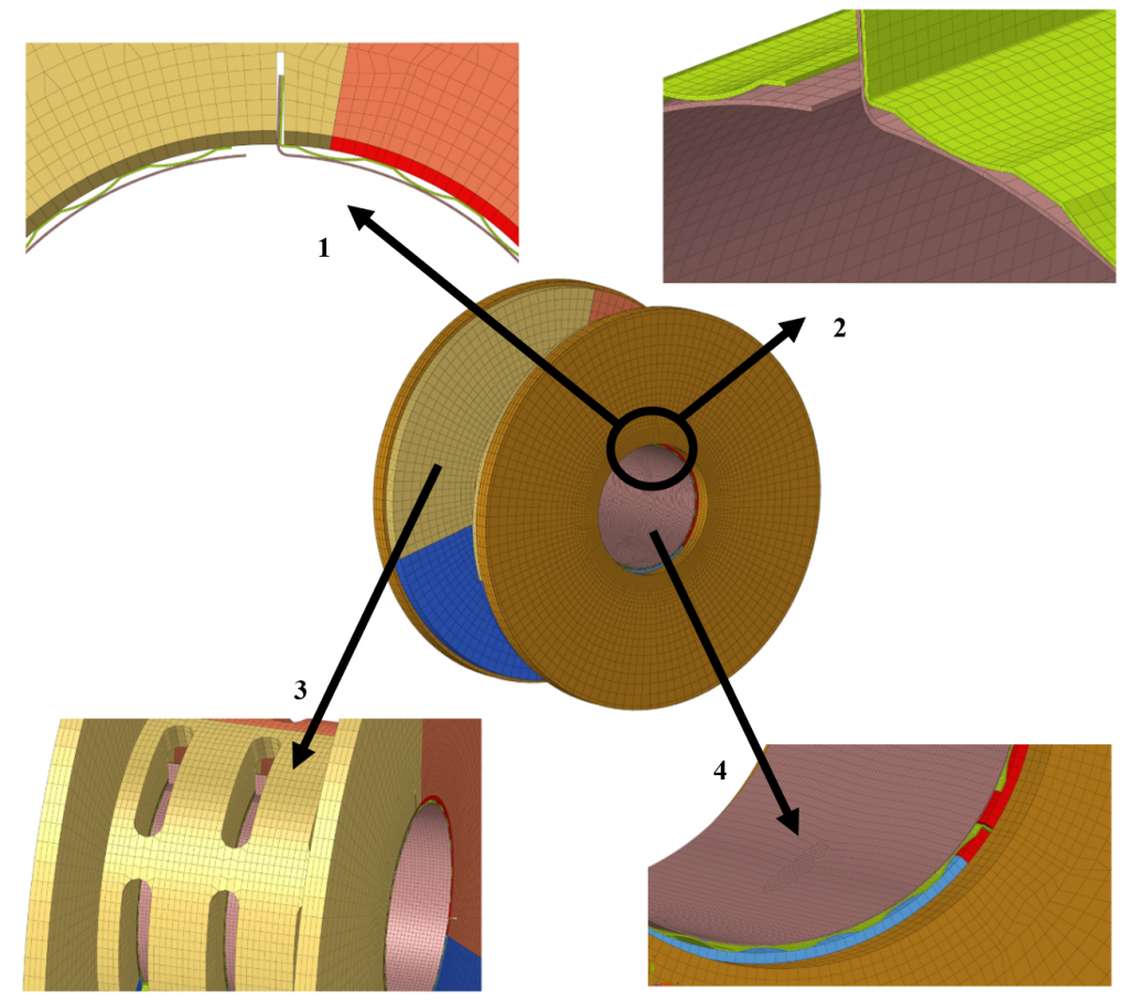
Finite element (FE) simulations have been carried out to determine spatial distributions of temperature and strain in the selected components of the designed GFB. Figure below shows FE model created based on the elborated CAD model.
FE model
Structural components of the investigated GFB modeled as FEs (see figure): 1, 2 – cross-sectional and isometric views on the top and bump foils, 3 – a single part of the bearing’s tricuspid bushing shell shown with openings for wires, 4 – inner surface of the top foil.
The FE model includes: tricuspid bushing shell, thrust flanges, top foil and bump foils. The following software has been employed for FE analyses: Altair HyperMesh (pre-procesor), MSC Software.Marc (solver) and Altair HyperView (post-procesor). The boundary conditions declare arbitrarily set pressure and temperature distributions in the top foil. Having considered high flexibility of the foils with respect to the rest of the GFB’s structural components, bushing’s shell and flange are modeled as fixed rigid bodies. Moreover, fixed displacements are used to keep the folded ends of the top and bump foils at correct locations in the bushing tierces.
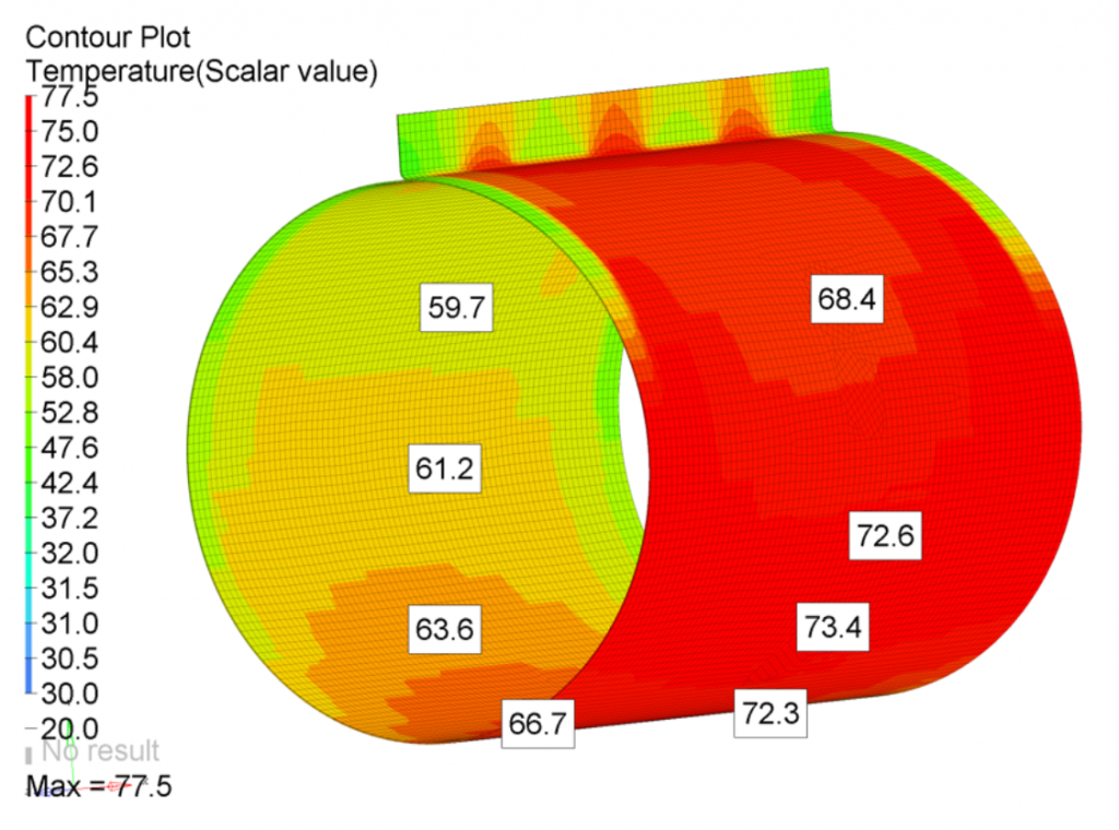
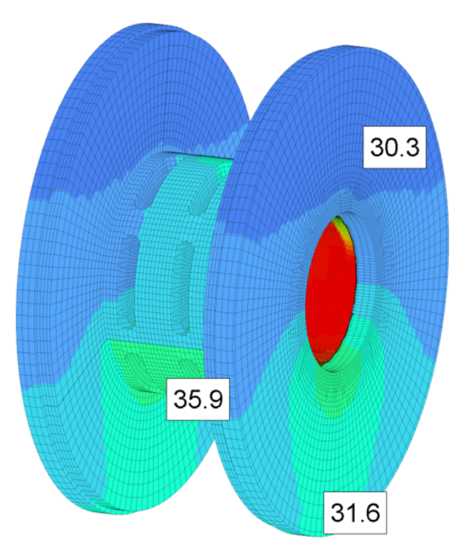
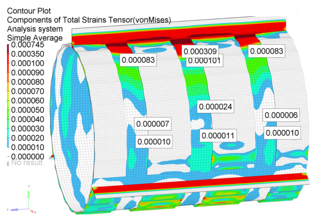
Figures below present temperature and strain distributions identified in the FE simulations.
Temperature distribution in a top foil
Temperature distribution in a spool-shaped bushing